80m..10m shortwave transceiver with SI5351A clock generator
I have a dream. Once in my life I'll have fluent English. Till then I owe all English people an apology.
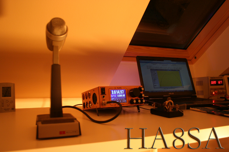
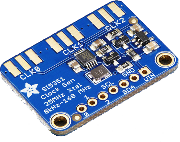
When I decided to make the 5th transceiver of my life, I took into account several conditions. The most important criterion was for me, that the radio won't be a neverending story. My last transceiver had been making for seven years and I could established many nice DX qso on lower bands. I thought, until I get enough power for the next omniscient radio building I try to make a simple trx. While surfing on the web I found VU2ESE developed Minima qrp transceiver. This radio gave the idea, that I make a similar 'do it if you have free time' trx. I was lucky because Silicon Labs has launched Si5351a three channel clock generator at this time and NT7S has already written the library.
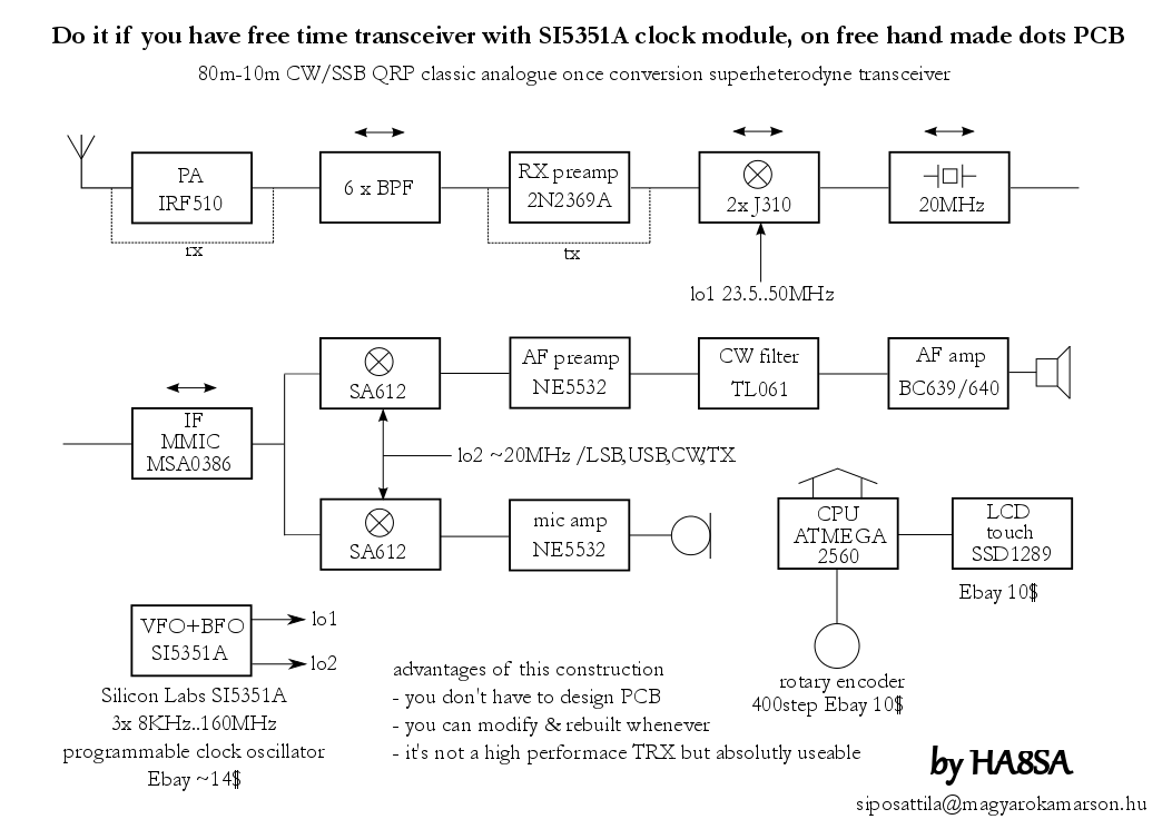
The radio's block diagram:
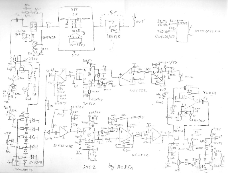
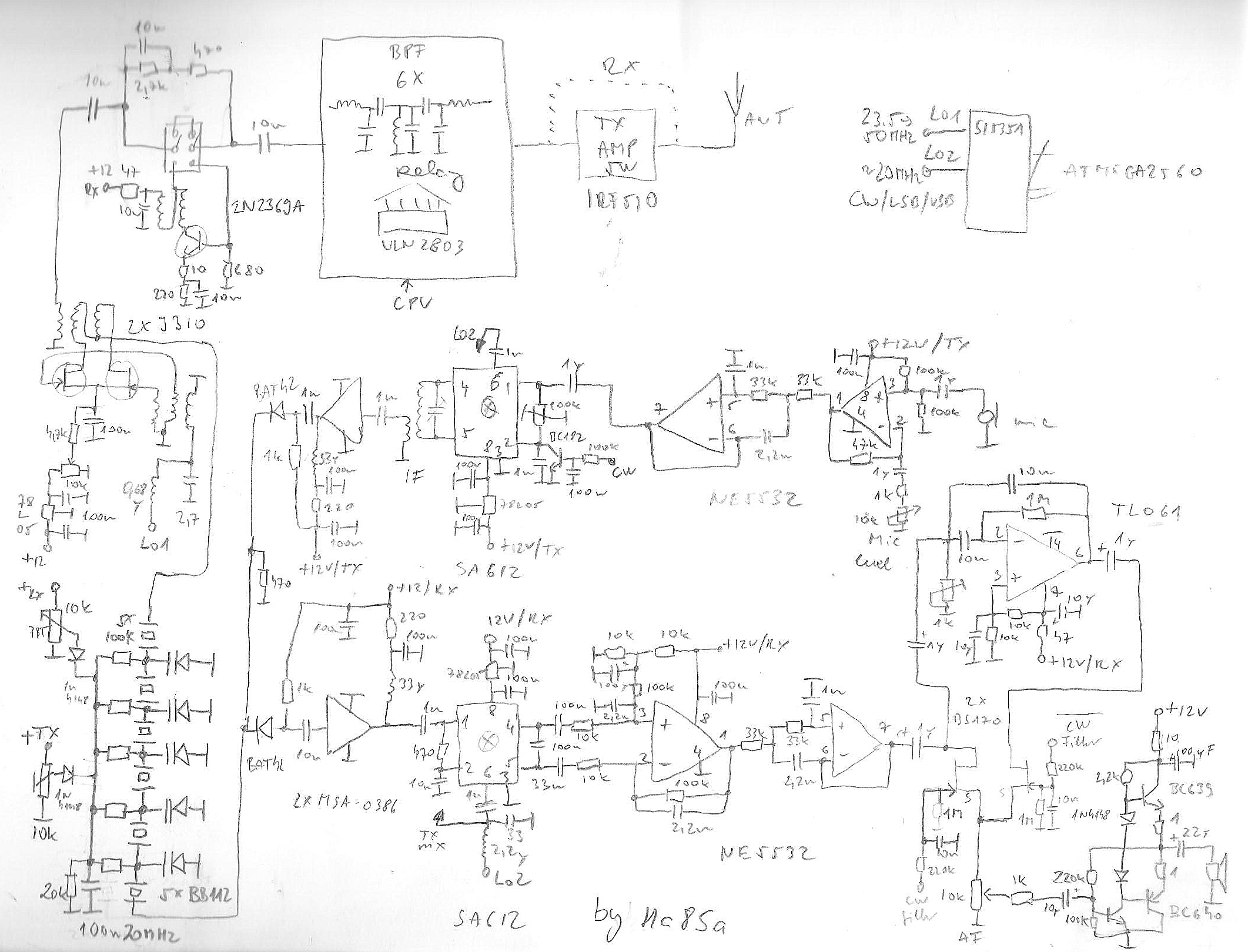
Schematic draw with BIOCAD software:) <larger size>
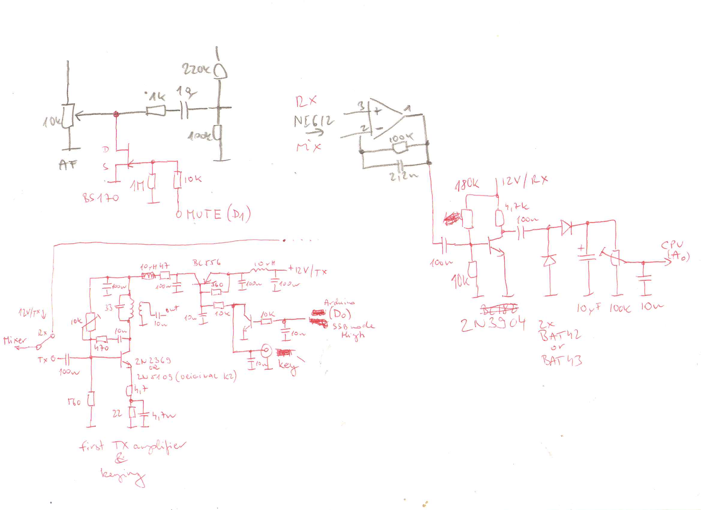
the missing parts of schematic (mute, keyer, s-meter)
Structure of radio:
In case of receiving the signal from antenna bypasses power amplifier. The bandpass filter was only made with micro-inductors and SMD capacitors. I know it's not the best solution but absolutely viable. The filter design is based on YU1LM's documentation. I switch beetwen the bands with relays because I had a lot of intermodulation problem with diodes.
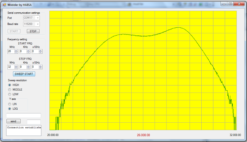
24MHz--28MHz BPF response curve (of course homebrew analyser)
A preamplifier helps to receive weak signals mainly on upper bands. During transmission this amp doesn't work. Bidirectional mixer works with two selected J310 FET pair. The IF filter includes six selected 20MHz crystals. We can control filter's bandwidth with front panel potenciometer between 500Hz and 5KHz.
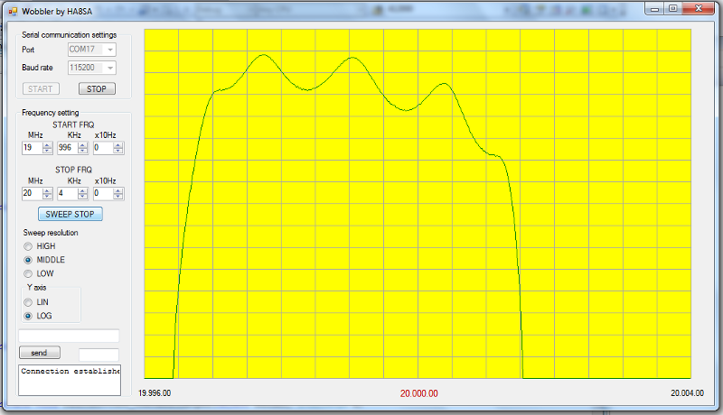
IF filter bandwidth at 5KHz (6V on diodes)
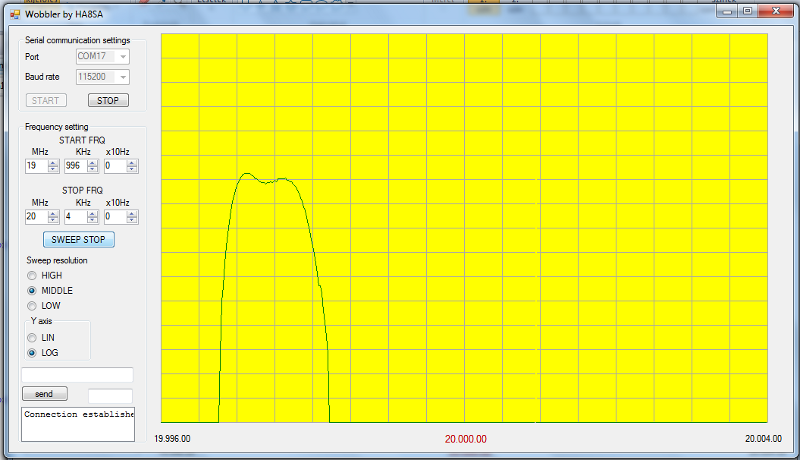
IF filter bandwidth at 1.5KHz (3V on diodes)
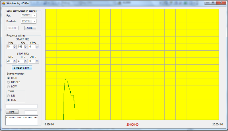
IF filter bandwidth at 500Hz (2V on diodes)
PIN diodes switched IF signal which is amplified with similar MSA-0386 MMIC in both (rx & tx) case. Product detector is a double balanced mixer (SA612). A NE5532 OPA filters (3KHz LPF) and amplifiers the audio signal for power amplifier. I've never used popular LM386 because it has a high noisy level. I can switch on an efficient CW filter what I made with only one TL061 OPA.
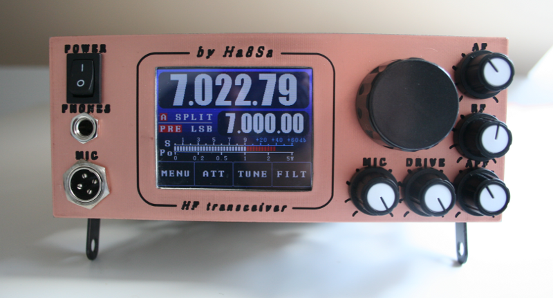
Front panel with 3.2" TFT LCD
Every mechanic parts are made with homebrew -of course- CNC milling machine:)
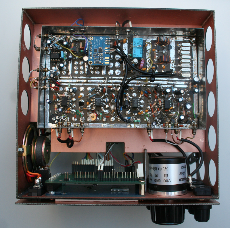
Top view
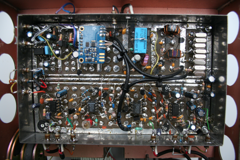
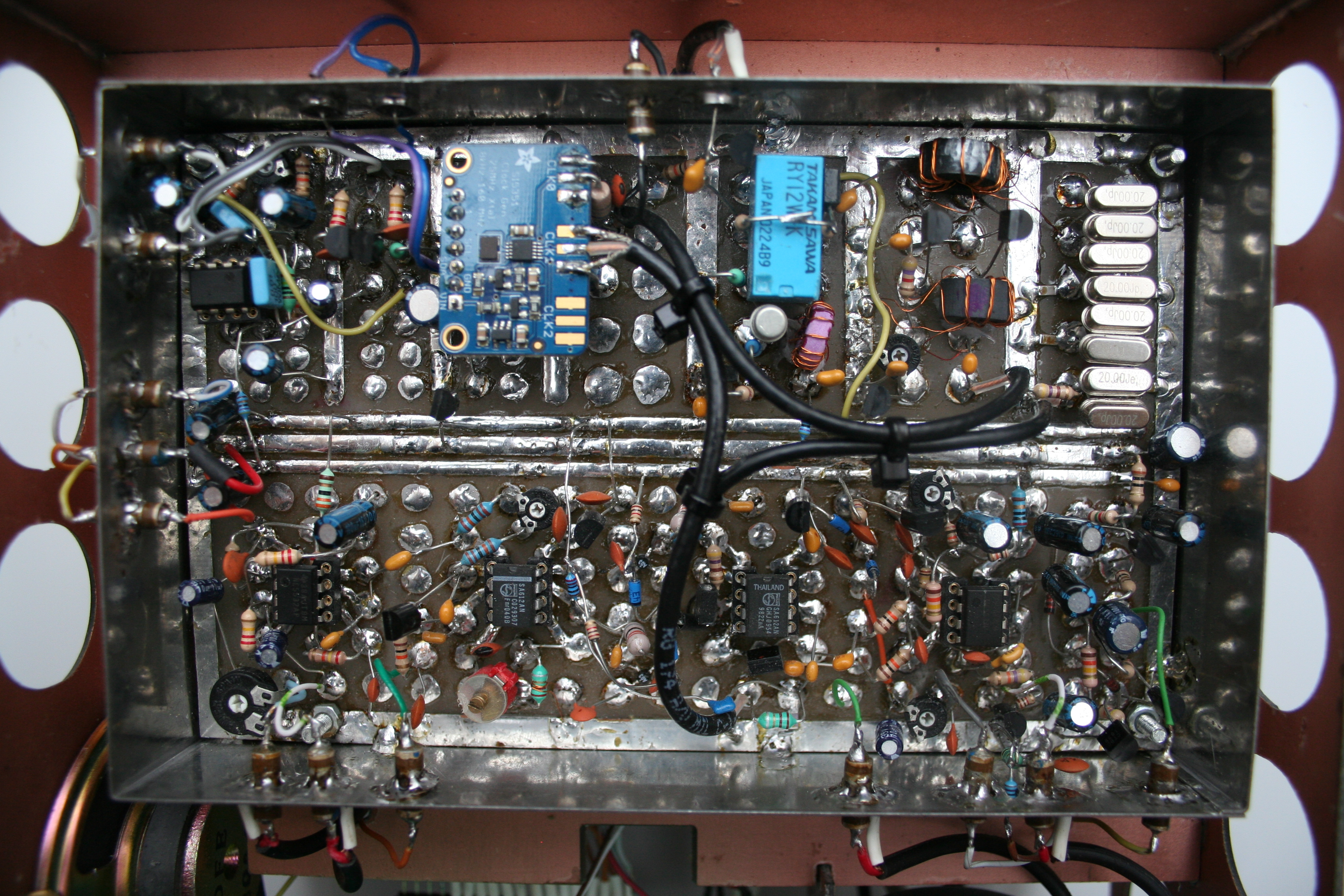
All circuit without PA and BPF module <larger size>
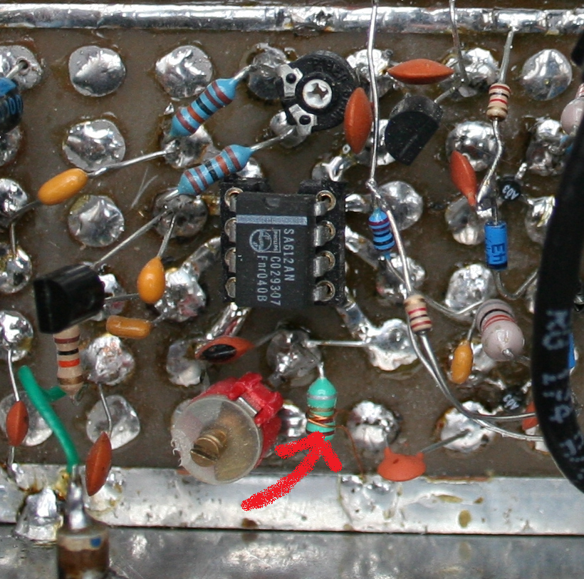
DSB generator & output resonant circuit
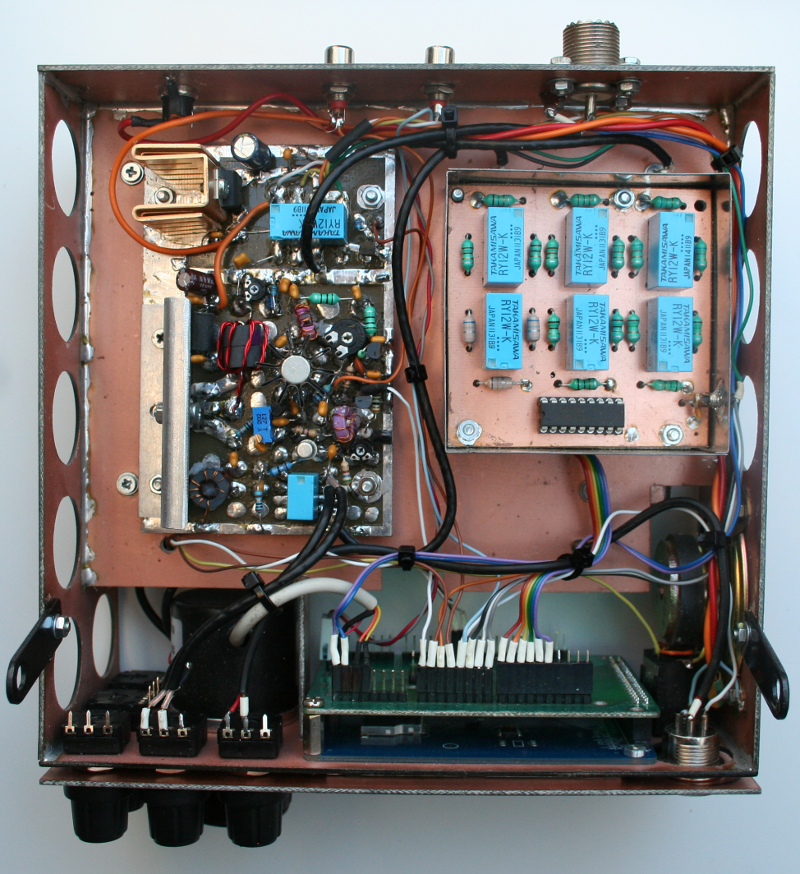
Bottom view (PA, BPF)
In transmission case, the microphone's sign amplifiers and cuts (LPF 3KHz) a NE5532 OPA. The 20MHz IF DSB signal is generated with a SA612. The double balanced mixer is tilted by transistor during CW mode.
First local oscillator (23.5..53.5MHz) and beat oscillator (~20MHz, depend of LSB or USB) are using the same SI5351A IC because the module has 3 independed programable (8Khz..160MHz) channel. Both channels are filtered by LC LPF. Of course I know this module has a big problem with SPUR signal when we use more than one channel in the same time. In practice I didn't find some disadvantage. It's a simple radio with simple parts but really absolutely useable.
HF power amplifier is a classic QRP with IRF510. I use a DRAKE MN7 tuner end of amplifier.
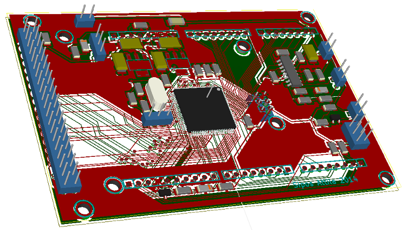
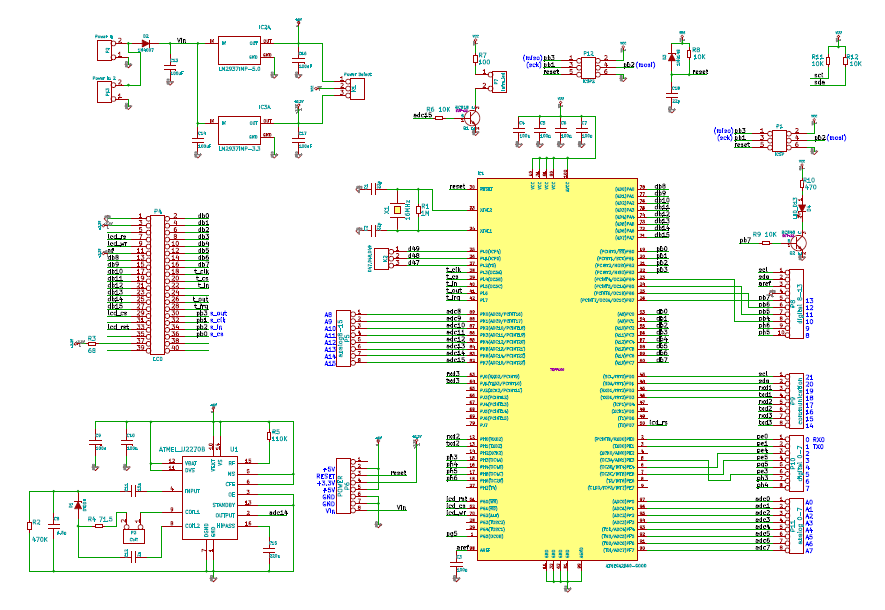
I have some other projects and I designed an arduino compatible board with atmega2560. I wrote the program on arduino IDE enviroment. You can download the source code <from>. I've tested this program under arduino1.6.13 with latest utft library. I needed to change the UTFT library with new fonts and function <here>. Because the name of UTouch library changed URTouch you have to write it into source code!
The code with highlighted input and output connections <here>. I ordered the TFT panel on Ebay as rotary encoder too.

Video:
The reasons that I wrote this short description only two things. Firstly: the dotty PCB is a very helpful system for a lazy amateur. When I have had a little free time I soldered some parts. If I wanted to change something just did it and I didn't have to make a new PCB. Secondly: I use this radio every day with pleasure so I have enough time to design and make an experiment for a new 6th ham radio.
73 & DX!
Attila